
●General Information
Sector gate is suitable for all kinds of ore, coal, coke and ash, chemical products, which the bulk density of 2.5 t/m3 or less. It is widely used for Silo's bottom discharge of building materials, metallurgy, chemical industry, glass industry, etc.
●Structural Characteristics
Sector gate adopts qualitative carbon steel welding, unique structure, flexible and reliable running, without jam phenomenon. With different transmission devices can meet the needs of the different operating conditions. The electric sector gate uses electric push rod with overload protection device, can avoid burning motor, and can realize the telecontrol or program control, reciprocating travel can be finely adjusted position self-locking. Electric hydraulic sector gate adopts electric hydraulic push rod, full hydraulic pressure drive, push or pull all can realize stepless speed regulation. Pneumatic sector gate adopts pneumatic push rod, through a combination of accessories can realize the telecontrol or field control. SEF is for manual, DEF is for electric, Y is for electric hydraulic and QEF is for pneumatic.
●Work Principle
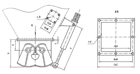
Sector gate consists of body, fan shape gate plate, shaft, gears, seals, actuator and other components. Manual or actuator drives the rocker, gear drive fan shape gate plate rotates along the axis, the two fan shape to open both sides, then material falling as soon as possible, after fill up the material receive device, then the actuator drives the rocker, the fan shape gate plate will reset, close and cut the falling materials.
●Technical Parameters
Temperature | Bulk Proportion | Applicable Medium |
≤300℃ | ≤2.5t/m3 | Crystalline solid, coal, coke, ash, chemical products and mineral stones |
●Transmission Device Parameters
Type | 200 | 300~400 | 700~800 | 700~800 | 900~1000 |
Suitable Pressure(kg) | 89 | 185~240 | 1130~1720 | 1130~1720 | 2110~2950 |
Electric Push Rod | DTⅠA500M P:0.37kw | DTⅠA500M P:0.75kw | DTⅠA700M P:1.1kw | DTⅠA1000M P:1.1kw | DTⅠA1600M P:2.2kw |
Electric-hydrauliuc Push Rode | DYT300 P:0.37kw | DYT450 P:0.55kw | DYT700 P:0.75kw | DYT1000 P:1.1kw | DYT1500 P:1.5kw |
Pneumatic Push Rod | 10A-5V CA 100B | 10A-5V CA 100B | 10A-5V CA 125B | 10A-5V CA 160B | 10A-5V CA 200B |
EF-C External Drawing:
EF-C External Connection Dimension
A×A | B×B | C×C | b | E | F | n-d | H | N | M | Φ |
200×200 | 245×245 | 280×280 | 6 | 90 | 350 | 8-Φ12 | 280 | 280 | 320 | 26 |
300×300 | 355×355 | 400×400 | 8 | 100 | 400 | 12-Φ12 | 300 | 300 | 320 | 26 |
400×400 | 455×455 | 500×500 | 8 | 120 | 460 | 16-Φ14 | 360 | 360 | 320 | 26 |
500×500 | 555×555 | 600×600 | 10 | 150 | 510 | 20-Φ14 | 480 | 480 | 320 | 26 |
600×600 | 655×655 | 700×700 | 10 | 180 | 560 | 20-Φ14 | 600 | 600 | 320 | 26 |
700×700 | 755×755 | 800×800 | 12 | 220 | 610 | 20-Φ14 | 660 | 660 | 360 | 32 |
800×800 | 855×855 | 900×900 | 12 | 240 | 660 | 24-Φ14 | 760 | 760 | 360 | 32 |
900×900 | 955×955 | 1000×1000 | 14 | 280 | 720 | 24-Φ14 | 900 | 900 | 360 | 32 |
1000×1000 | 1070×1070 | 1130×1130 | 14 | 350 | 880 | 28-Φ18 | 1040 | 1040 | 360 | 32 |
Instructions:
1. Please mark the flow direction of the medium on the body of the gate. There should add gasket when connect the flanges and then lock the bolt tightly.
2. Please check the direction of the fan shape gate plate when running and connect the actuator correctly.
3. Please add lubricate oil on the transmission parts regularly.