
●General Information
This series of 3-way, 4-way diverter valve is widely used in building materials, metallurgy, mining, light industry, grain, etc. It is the perfect equipment to change the flow direction of solid crystalline grain and powdery material in the output system.
●Structure Characteristics
The valve adopts high quality carbon steel welding, and equipped with different actuator according to different needs. It has characteristics of light and wear-resistant, clearly open gatage, convenient switch, flexible operation, etc.
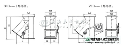
Ⅰ is the side 3-way diverter valve, Ⅱ is the positive 3-way diverter valve, Ⅲ is 4-way diverter valve. The drive ways as follows:S is manual, D is electric, Z is automatic, Q is pneumatic, and Y is electro-hydraulic.
●Work Principle
3-way, 4-way mainly consists of body, the material diverter plate, transmission shaft, the bearing pedestal, seal part, rocker, transmission device, etc. The manual 3-way, 4-way diverter valve switches the medium flow by manhandle pushing the punch of the rocker bases on different work situation. The electric 3-way, 4-way diverter valve switches the medium flow by electrifying the DT electric push rod through the command control that will push the rotation valve shaft of the rocker bases on different work situation. The automatic 3-way, 4-way, diverter valve is equipped with DKJ electric actuator which will receive, change and send, adjust the control signal or the manual control signal of manipulator of DCS,PLC, etc. level gage. The customer can control the gatage of the diverter plate by controlling the electricity signal which can realize the adjustment. The pneumatic 3-way, 4-way diverter valve is equipped with the QGB pneumatic parts and uses the double control two five-way control reversing valve to drive the pneumatic push rode to drive the rod. The rotate valve and the diverter plate could finish the switch of the medium flow direction. The electro-hydraulic 3-way, 4-way is equipped with DYT electro-hydraulic push rocker to drive the valve shaft and the diverter plate to finish the switch of the medium flow.
1. During the transportation, please avoid the striking. 3-way, 4-way diverter valve should keep close and in case of the plate and the transmission part damage in the transportation.
2. When the 3-way, 4-way diverter valve is transporting flatly, the transmission device and the drive part should overhead to prevent the out of shape and the damage of the transmission shaft under too much pressure.
3. The transmission device and part should add rain-proof and moisture-proof measures.
4. The 3-way, 4-way diverter valve should store in the dry room instead of putting in the opening air or pile up. If the diverter valve will in a long-term spare time, please keep them closed. The transmission device should add rain-proof and moisture-proof measures.
●Maintenance and Overhaul
1. Please check the work situation of the transmission parts regularly.
2. Please periodic replace the lubricating oil, the grease of the electric push rod, power oil of the electro-hydraulic push rod (150 engine oil) so that it will ensure the mechanical parts won't get damaged.
3. Please periodic check the seal situation of 3-way, 4-way diverter valve's spindle regularly. If there question of the sealing, please replace or add the graphite packing.
4. Please check the gasket of the electro-hydraulic and pneumatic push rod so that it will ensure the normal running of the transmission device.
●Ordering Instruction
1. When placing the order, please refer to the sample's type, size, angle, technical parameters (temperature, equipment working conditions, medium, performance, etc.)
2. The transmission device in the picture of the sample is our basic equipment; if there is any special requirement (anti-explosion, outdoor, adjustable, switch, etc.), we could allocate other transmission device. Please refer to the allocation instruction attached with the samples to choose the transmission device, and mark behind the basic type.
3. When placing the order, if there is no special mark from the customers, the transmission code will be equipped the basic type of our company and the basic type is the normal device without any special requirement and accessories.
4. If there does not mark the type, use for special medium or other special requirements in the table, please contact with our sales and technical department. We could design and manufacture.
●Technical Parameters
Work Pressure | Temperature | Medium |
0.1MPa | ≤300℃ | Crystalline grain, particle, powdery material, etc. |
●Transmission Device Parameters
Type | 200~250 | 300~400 | 500~600 | 700~800 |
Electric Push Rod | DTⅠA63-M P:0.06KW | DTⅠA63-M P:0.09KW | DTⅡA100-M P:0.25KW | DTⅡA250-M P:0.37KW |
Automatic Device | DKJ -210 P:0.025KW | DKJ -310 P:0.025KW | DKJ -410 P:0.16KW | DKJ -510 P:0.25KW |
Pneumatic Push Rod | 10A-5TC50B | 10A-5TC63B | 10A-5TC80B | 10A-5TC100B |
Electro-hydraulic Push Rod | DYT100 P:0.37KW | DYT300 P:0.37KW | ||

FC-I External Connection Dimension
A | B | C | α | H | H1 | L | n-d | L1 | L2 | L3 | L4 | L5 | L6 |
200×200 | 245×245 | 280×280 | 45° | 530 | 394 | 289 | 8-Φ10 | 180 | 220 | 220 | 290 | 320 | 340 |
50° | 600 | 445 | 293 | ||||||||||
55° | 650 | 505 | 290 | ||||||||||
60° | 735 | 594 | 295 | ||||||||||
250×250 | 305×305 | 350×350 | 45° | 605 | 448 | 338 | 12-Φ10 | 220 | 250 | 250 | 310 | 345 | 410 |
50° | 675 | 512 | 342 | ||||||||||
55° | 735 | 595 | 346 | ||||||||||
60° | 820 | 706 | 355 | ||||||||||
300×300 | 355×355 | 400×400 | 45° | 690 | 499 | 374 | 12-Φ12 | 250 | 280 | 280 | 375 | 370 | 440 |
50° | 750 | 568 | 380 | ||||||||||
55° | 820 | 658 | 380 | ||||||||||
60° | 910 | 791 | 405 | ||||||||||
400×400 | 455× 455 | 500×500 | 45° | 825 | 598 | 463 | 16-Φ12 | 280 | 350 | 325 | 425 | 420 | 470 |
50° | 930 | 709 | 490 | ||||||||||
55° | 1020 | 859 | 504 | ||||||||||
60° | 1155 | 1005 | 505 | ||||||||||
500×500 | 555×555 | 600×600 | 45° | 1000 | 755 | 575 | 20-Φ14 | 350 | 385 | 395 | 480 | 500 | 520 |
50° | 1110 | 888 | 597 | ||||||||||
55° | 1250 | 1052 | 632 | ||||||||||
60° | 1425 | 1260 | 647 | ||||||||||
600×600 | 655×655 | 700×700 | 45° | 1297 | 921 | 706 | 20-Φ14 | 400 | 450 | 450 | 540 | 550 | 570 |
50° | 1430 | 1097 | 742 | ||||||||||
55° | 1500 | 1223 | 731 | ||||||||||
60° | 1677 | 1481 | 768 | ||||||||||
700×700 | 755×755 | 800×800 | 45° | 1450 | 1029 | 779 | 20-Φ14 | 450 | 500 | 500 | 630 | 620 | 650 |
50° | 1520 | 1163 | 809 | ||||||||||
55° | 1708 | 1421 | 850 | ||||||||||
60° | 1863 | 1646 | 850 | ||||||||||
800×800 | 855×855 | 900×900 | 45° | 1555 | 1125 | 860 | 24-Φ14 | 500 | 550 | 550 | 680 | 670 | 700 |
50° | 1702 | 1327 | 907 | ||||||||||
55° | 1892 | 1594 | 946 | ||||||||||
60° | 2145 | 885 | 913 |
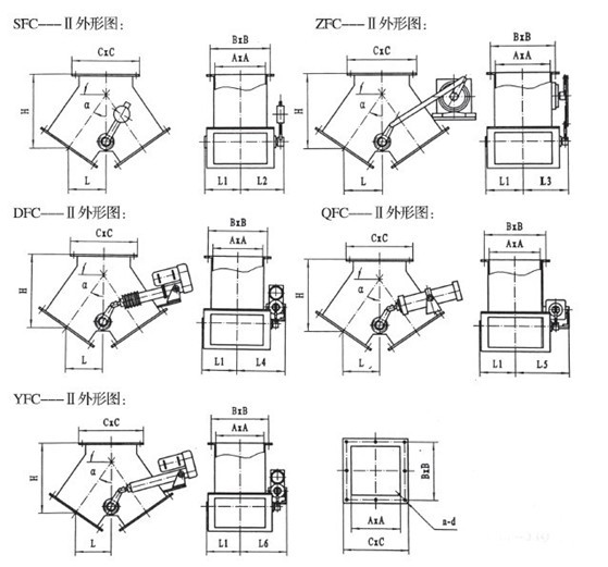
FC-II External Connection Dimension
A | B | C | α | H | L | n-d | L1 | L2 | L3 | L4 | L5 | L6 |
200×200 | 245×245 | 280×280 | 45° | 267 | 177 | 8-Φ10 | 180 | 220 | 220 | 290 | 320 | 340 |
50° | 282 | 174 | ||||||||||
55° | 299 | 161 | ||||||||||
60° | 352 | 160 | ||||||||||
250×250 | 305×305 | 350×350 | 45° | 298 | 198 | 12-Φ10 | 220 | 250 | 250 | 310 | 345 | 410 |
50° | 330 | 193 | ||||||||||
55° | 338 | 181 | ||||||||||
60° | 396 | 182 | ||||||||||
300×300 | 355×355 | 400×400 | 45° | 322 | 212 | 12-Φ12 | 250 | 280 | 280 | 375 | 370 | 440 |
50° | 349 | 209 | ||||||||||
55° | 386 | 204 | ||||||||||
60° | 431 | 200 | ||||||||||
400×400 | 455× 455 | 500×500 | 45° | 381 | 251 | 16-Φ12 | 280 | 350 | 325 | 425 | 420 | 470 |
50° | 419 | 251 | ||||||||||
55° | 448 | 244 | ||||||||||
60° | 525 | 245 | ||||||||||
500×500 | 555×555 | 600×600 | 45° | 470 | 310 | 20-Φ14 | 350 | 385 | 395 | 480 | 500 | 520 |
50° | 532 | 320 | ||||||||||
55° | 557 | 290 | ||||||||||
60° | 644 | 300 | ||||||||||
600×600 | 655×655 | 700×700 | 45° | 502 | 290 | 20-Φ14 | 400 | 450 | 450 | 540 | 550 | 570 |
50° | 561 | 310 | ||||||||||
55° | 643 | 330 | ||||||||||
60° | 738 | 340 | ||||||||||
700×700 | 755×755 | 800×800 | 45° | 617 | 380 | 20-Φ14 | 450 | 500 | 500 | 630 | 620 | 650 |
50° | 678 | 400 | ||||||||||
55° | 795 | 420 | ||||||||||
60° | 937 | 442 | ||||||||||
800×800 | 855×855 | 900×900 | 45° | 672 | 408 | 24-Φ14 | 500 | 550 | 550 | 680 | 670 | 700 |
50° | 763 | 445 | ||||||||||
55° | 900 | 482 | ||||||||||
60° | 1057 | 493 |
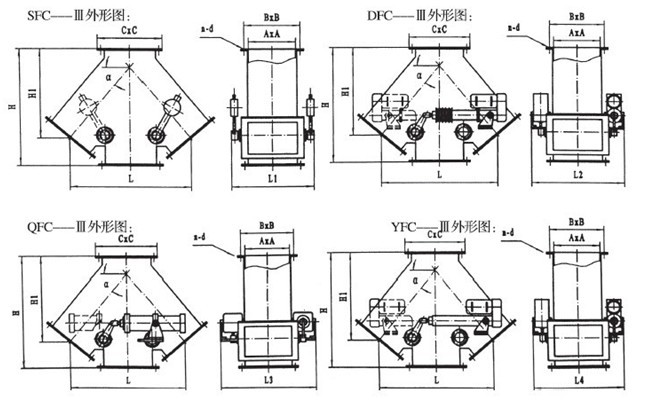
FC-III External Connection Dimension
A | B | C | α | H | H1 | L | n-d | L1 | L2 | L3 | L4 |
200×200 | 245×245 | 280×280 | 45° | 530 | 394 | 578 | 8-Φ10 | 440 | 580 | 640 | 680 |
50° | 600 | 445 | 586 | ||||||||
55° | 650 | 505 | 580 | ||||||||
60° | 735 | 594 | 590 | ||||||||
250×250 | 305×305 | 350×350 | 45° | 605 | 448 | 676 | 12-Φ10 | 500 | 620 | 690 | 820 |
50° | 675 | 512 | 684 | ||||||||
55° | 735 | 585 | 692 | ||||||||
60° | 820 | 656 | 710 | ||||||||
300×300 | 355×355 | 400×400 | 45° | 690 | 499 | 748 | 12-Φ12 | 560 | 750 | 740 | 880 |
50° | 750 | 568 | 760 | ||||||||
55° | 820 | 638 | 760 | ||||||||
60° | 910 | 741 | 810 | ||||||||
400×400 | 455× 455 | 500×500 | 45° | 825 | 598 | 926 | 16-Φ12 | 650 | 850 | 840 | 940 |
50° | 930 | 699 | 980 | ||||||||
55° | 1020 | 784 | 1008 | ||||||||
60° | 1155 | 935 | 1010 | ||||||||
500×500 | 555×555 | 600×600 | 45° | 1000 | 730 | 1150 | 20-Φ14 | 790 | 960 | 1000 | 1040 |
50° | 1110 | 838 | 1194 | ||||||||
55° | 1250 | 972 | 1264 | ||||||||
60° | 1425 | 1170 | 1294 | ||||||||
600×600 | 655×655 | 700×700 | 45° | 1297 | 921 | 1412 | 20-Φ14 | 900 | 1080 | 1100 | 1140 |
50° | 1430 | 1027 | 1484 | ||||||||
55° | 1500 | 1133 | 1462 | ||||||||
60° | 1677 | 1351 | 1536 | ||||||||
700×700 | 755×755 | 800×800 | 45° | 1450 | 1029 | 1558 | 20-Φ14 | 1000 | 1260 | 1240 | 1300 |
50° | 1520 | 1128 | 1618 | ||||||||
55° | 1708 | 1311 | 1700 | ||||||||
60° | 1863 | 1506 | 1700 | ||||||||
800×800 | 855×855 | 900×900 | 45° | 1555 | 1125 | 1720 | 24-Φ14 | 1100 | 1360 | 1340 | 400 |
50° | 1702 | 1232 | 1814 | ||||||||
55° | 1892 | 1449 | 1892 | ||||||||
60° | 2145 | 1735 | 1826 |