
●General Information
The airlock flap discharge valve is widely used as the ash bucket discharge device of different dust collectors in the building materials, metallurgy, petrochemical engineering, electricity power, light industry, etc. And it also could be used as the airlock or discharge device of variety grind machine, dry machine, storage bin, silo and closed conveying system, etc.
●Structure Characteristics
The airlock flap discharge valve opens and shuts alternately between up one and down one. The automatic reset mechanism is divided into Z heavy punch automatic reset mechanism which has characteristics of stable running, energy-saving, large discharge capability, and reliable airlock. C is the drive hammer automatic reset mechanism which has characteristics of small area using, energy -saving, convenient discharge adjustment, reliable discharge and airlock. B is cam, connecting rod transmission, weight automatic reset mechanism. D is cam, connecting rod transmission; spring automatic reset mechanism which has the characteristics of compact structure, reasonable design, stable running, reliable discharge and airlock. It is perfect equipment of feeder and discharge for no viscosity, and less Φ10mm particle material, crystal grain, mass of liquid material, .I-single plate discharge, II- double plates discharge.
●Work Principle
Airlock flap discharge valve mainly consists of valve body, valve plate, valve shaft, rocker, etc. I type is the single layer .With the program which set by the electric-pneumatic control system, it pushes rocker to drive the valve plate by the push rod to start discharge then close. II type pushes rocker to drive the valve plate by the push rod to start discharge and airlock. With the program which set by the electric-pneumatic control system, the up and down valve plate open and close alternately. These two actions will keep one of plates of the pipe close so that makes discharge and airlock at the same.
Heavy hammer airlock flap discharge valve mainly consists of valve body, valve plate, valve shaft, rocker, heavy hammer, etc. It uses the moment balance to realize the airlock discharge. When the moment which affect on the material on the plate is bigger than one produced by the heavy hammer, the plate will open and begin to discharge. And as finishing discharging materials, the moment of heavy hammer and rocker makes valve plate quickly; the airlock is because of the double layer structure so there is one plate always keep closed. And this makes discharge and airlock at the same.
Electric airlock flap discharge valve mainly consists of valve body, valve plate, rocker, connecting rod, cam, spring, etc. It uses cam, connecting rod and spring continuous act to realize the airlock discharge. The cam system is electric pneumatic control so that the open angle and time could be controlled in certain range by the reducer. The reducer drive the cam rotated to the up half-cycle, because interaction of connecting rod of the upper valve, the valve plate open and start to discharge. As the rotating of the cam, the spring mechanism reset and closes gradually. The cam rotates downside half-cycle, because interaction of connecting rod of the down valve, the valve gate opens and discharges gradually. With the rotation of the cam the valve closes gradually. These two actions will keep one of plates of the pipe close so that makes discharge and airlock at the same.
●Technical Parameters
Medium | Temperature | Discharge Capability |
Dry Powdery Material, particle, crystal grain, etc. | 150℃ | 3~168 m3/h |
JSX Series Appearance
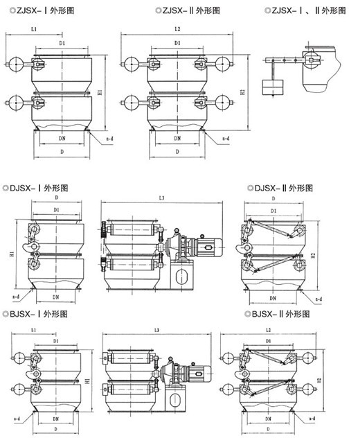
JSX Series External Connection Dimension
DN | D | D1 | H1 | H2 | L1 | L2 | L3 | n-d | Transmission Device | Power |
150 | 230 | 195 | 500 | 460 | 1400 | 8-Φ10 | BWY-15-59 | 0.6 | ||
200 | 280 | 245 | 600 | 500 | 1500 | 8-Φ10 | BWY-15-59 | 0.6 | ||
220 | 300 | 265 | 620 | 520 | 1540 | 8-Φ10 | BWY-15-59 | 0.6 | ||
250 | 350 | 305 | 650 | 560 | 1610 | 12-Φ10 | BWY-18-71 | 0.8 | ||
300 | 400 | 355 | 750 | 540 | 600 | 1220 | 1840 | 12-Φ10 | BWY-22-71 | 1.1 |
320 | 420 | 375 | 780 | 560 | 620 | 1260 | 1980 | 12-Φ12 | BWY-22-71 | 1.1 |
400 | 500 | 455 | 950 | 700 | 815 | 1500 | 2060 | 16-Φ12 | BWY-2215-121 | 1.66 |
450 | 550 | 505 | 1050 | 800 | 840 | 1550 | 2180 | 16-Φ12 | BWY-2215-121 | 1.66 |
500 | 600 | 555 | 1150 | 850 | 870 | 1600 | 2210 | 20-Φ14 | BWY-2215-121 | 1.66 |
600 | 700 | 655 | 1350 | 980 | 960 | 1920 | 2310 | 20-Φ14 | BWY-2215-121 | 1.66 |
720 | 820 | 775 | 1120 | 2220 | 2380 | 20-Φ14 | BWY-2715-121 | 3.18 | ||
800 | 900 | 855 | 1260 | 2520 | 2420 | 24-Φ14 | BWY-2715-121 | 3.18 | ||
1000 | 1130 | 1070 | 1500 | 2940 | 2640 | 28-Φ18 | BWY-3322-187 | 4.3 |
●Installation and Test
1. The transmission device should not be used for lifting and no damage.
2. Before installation, please clean the inside of the valve. There should no dirt and other things.
3. Please check the transmission parts before installation, and adjust the valve according to the customer's work system (there was standard adjustment before leaving factory) ,if there is no problem, please full close the valve then install it.
4. Please add gasket between the flanges. And tighten combined bolt evenly.
5. Please check if the turning direction of the motor and the cam (there is arrow mark on the valve body) are the same before you connect the power line. The check method as follow: Open the protect shell of the motor firstly. Manual rotate vane and adjust it to the arrow position. Inching motor and checking whether the cam is match the direction of arrow. If the direction is correction, please continuous use the equipment otherwise it is easy to cause the damage of the equipment. Please keep testing 3 hours. If there is no problem then it could be used for producing.
6. The heavy hammer discharge could ensure the quantity and frequency of discharging materials by adjusting the position of heavy hammer according to actual work situation.
●Transportation and Protection
1. During the transportation, please avoid the striking. Valve should keep close and in case of the butterfly plate and the transmission part damage in the transportation.
2. When the valve is transporting flatly, the transmission device and the drive part should overhead to prevent the out of shape and the damage of the transmission shaft under too much pressure.
3. The transmission device and part should add rain-proof and moisture-proof measures.
4. The valve should store in the dry room instead of putting in the opening air or pile up. If the diverter valve will in a long-term spare time, please keep them closed. The transmission device should add rain-proof and moisture-proof measures.
●Maintenance and Overhaul
1. Please check the work situation of the transmission parts regularly.
2. Please periodic replace the lubricating oil of the electric actuator so that it will ensure the mechanical parts won't get damaged.
3. Please periodic check the seal situation of valve's spindle regularly. If there question of the sealing, please replace or add the graphite packing.
4. Please check the gasket of the electro-hydraulic and pneumatic push rod so that it will ensure the normal running of the transmission device.