●General Information
GX screw conveyor is the use of screw type turn the material along the casing continuously for delivery. This machine is simple in structure, external size is small, low cost, safe operation, and can base on the technological requirements meet the multipoint feeding and discharging.
●Technical Parameters
Type | Main Technological parameters | Derive Device | Weight (kg) | |||||
Diameter | Length(m) | Output (Cement) (t/h) | Rotate Speed (r/min) | Reducer | Motor | |||
Type | Speed Ratio | Type | Power (kw) | |||||
GX200 | ~10 | 9 | 60 | JZQ250 | 23. 34 | Y90S-4 | 1.1 | 726 |
GX200 | ~20 | 9 | 60 | JZQ250 | 23. 34 | Y90L-4 | 1.5 | 1258 |
GX250 | ~10 | 15.6 | 60 | JZQ250 | 23. 34 | YlOOL2-4 | 2.2 | 960 |
Gx250 | ~20 | 15.6 | 60 | JZQ250 | 23. 34 | Y100L1-4 | 3 | 1750 |
GX300 | ~10 | 21.2 | 60 | JZQ350 | 23. 34 | Y100L2-4 | 3 | 1373 |
GX300 | ~20 | 21.2 | 60 | JZQ350 | 23. 34 | Y112M-4 | 4 | 2346 |
GX400 | ~10 | 51 | 60 | JZQ400 | 23. 34 | Y132S-4 | 5.5 | 1911 |
GX400 | ~20 | 51 | 60 | JZQ500 | 23. 34 | Y160M-4 | 11 | 2049 |
Gx500 | ~10 | 87.5 | 60 | JZQ400 | 23. 34 | Y132M-4 | 7.5 | 2381 |
GX500 | ~20 | 87.5 | 60 | JZQ650 | 23. 34 | Y180M-4 | 18.5 | 5389 |
Gx600 | ~10 | 134.2 | 45 | JZQ750 | 23. 34 | Y180L-4 | 22 | 3880 |
Gx600 | ~10 | 134.2 | 45 | JZQ850 | 23. 34 | Y250M-4 | 55 | 7090 |
●Method and Installation Instruction
GX Screw Conveyor according to the requirements of different using situations is divided in two types: the method S and D method.
S method - screw with entity screw surface, the pitch is equal to 0.8 times of the diameter.
D method - screw with belt type screw surface, the pitch is equal to the diameter.
GX Screw Conveyor according to the drive assembly method is different, divided into right and left two kinds:
Right - stand to look ahead at the end of the motor, speed reducer shaft on the right side of the motor at low speed.
Left - stand to look ahead at the end of the motor, speed reducer to the left side of the shaft in the motor at low speed.
GX Screw Conveyor discharging mouth have square discharging mouth, hand push type discharging mouth and rack type discharging mouth. The later two discharging mouth's open and close direction of the pulling plate is divided into right installed and left installed according to the installation:
Right installation - standing on the right screw head quarter to look the tail section, the pulling plate is right pulled.
Left installation - standing on the screw head quarter to look the tail section, the pulling plate is left pulled.
●Installation Dimension and Length Combination

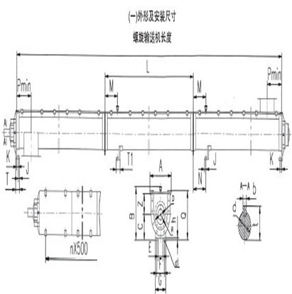
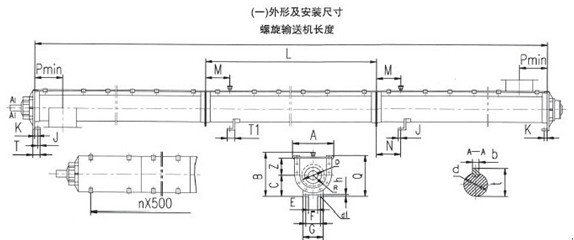
Installation Dimension
Diameter | A | B | C | E | F | G | H | K | J | M | N | Q | P | R | T | T1 | X | Z | d | d1 | a | f | I | I1 | b | t |
(kg) | (hs) | |||||||||||||||||||||||||
200 | 342 | 384 | 180 | 80 | 140 | 200 | 18 | 25 | 20 | 200 | 200 | 153 | 220 | 110 | 60 | 60 | 123 | 150 | 40 | 16 | 205 | 195 | 80 | 155 | 12 | 43.5 |
250 | 392 | 464 | 220 | 140 | 200 | 260 | 20 | 28 | 25 | 200 | 200 | 183 | 270 | 135 | 70 | 70 | 125 | 180 | 50 | 20 | 237 | 225 | 100 | 155 | 16 | 55 |
300 | 468 | 555 | 270 | 160 | 240 | 320 | 22 | 28 | 25 | 200 | 200 | 213 | 300 | 160 | 75 | 75 | 130 | 210 | 60 | 20 | 264 | 250 | 120 | 160 | 18 | 65.5 |
400 | 572 | 685 | 340 | 220 | 320 | 400 | 22 | 30 | 35 | 300 | 300 | 273 | 350 | 210 | 90 | 85 | 145 | 270 | 80 | 25 | 325 | 310 | 160 | 180 | 24 | 87 |
500 | 706 | 823 | 400 | 300 | 400 | 500 | 30 | 35 | 40 | 300 | 300 | 333 | 450 | 264 | 100 | 95 | 165 | 330 | 100 | 25 | 393 | 375 | 200 | 205 | 28 | 108 |
600 | 806 | 973 | 500 | 400 | 500 | 600 | 30 | 40 | 40 | 300 | 300 | 383 | 550 | 314 | 110 | 105 | 170 | 380 | 120 | 30 | 433 | 415 | 240 | 205 | 32 | 129 |
Note:1. The length of screw conveyor and the size L please check the table.
2. The n×500 in the picture is the size of the cover guard, n is decided by the screw length.
3. The size P is the center line of the outlet and inlet
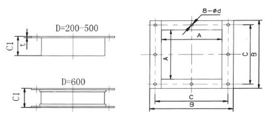
1. Feed Inlet:

Diameter | A | B | C | C1 | t | d | Weight/kg | Drawing No. |
200 | 220 | 306 | 272 | 100 | 3 | 9 | 3.64 | GX20-10-00 |
250 | 270 | 356 | 330 | 120 | 3 | 9 | 4.8 | GX25-10-00 |
300 | 320 | 428 | 386 | 140 | 4 | 13 | 8.88 | GX30-10-00 |
400 | 450 | 528 | 492 | 160 | 4 | 13 | 12.42 | GX40-10-00 |
500 | 528 | 662 | 612 | 160 | 4 | 17 | 16.56 | GX50-10-00 |
600 | 628 | 762 | 720 | 180 | 4 | 17 | 21.2 | GX60-10-00 |
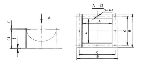
2. Square Discharge Mouth

A | B | C | E | F | G | H | K | J | Drawing No. |
200 | 226 | 312 | 272 | 165 | 8 | 3 | 9 | 4.36 | GX20-10-00 |
250 | 276 | 374 | 330 | 195 | 10 | 4 | 9 | 7.52 | GX25-10-00 |
300 | 328 | 426 | 386 | 225 | 10 | 4 | 13 | 9.36 | GX30-10-00 |
400 | 428 | 536 | 492 | 280 | 10 | 4 | 13 | 14.28 | GX40-10-00 |
500 | 536 | 670 | 612 | 340 | 15 | 4 | 17 | 26.14 | GX50-10-00 |
600 | 636 | 774 | 720 | 430 | 15 | 6 | 17 | 39.2 | GX60-10-00 |
Note:Screw diameter is 600 mm, the discharge mouth uses corner steel structure for exportation.


